Chapter 3
Methodology
The process for designing, developing, and testing the contour gauge for bamboo joinery.
Project Flowchart
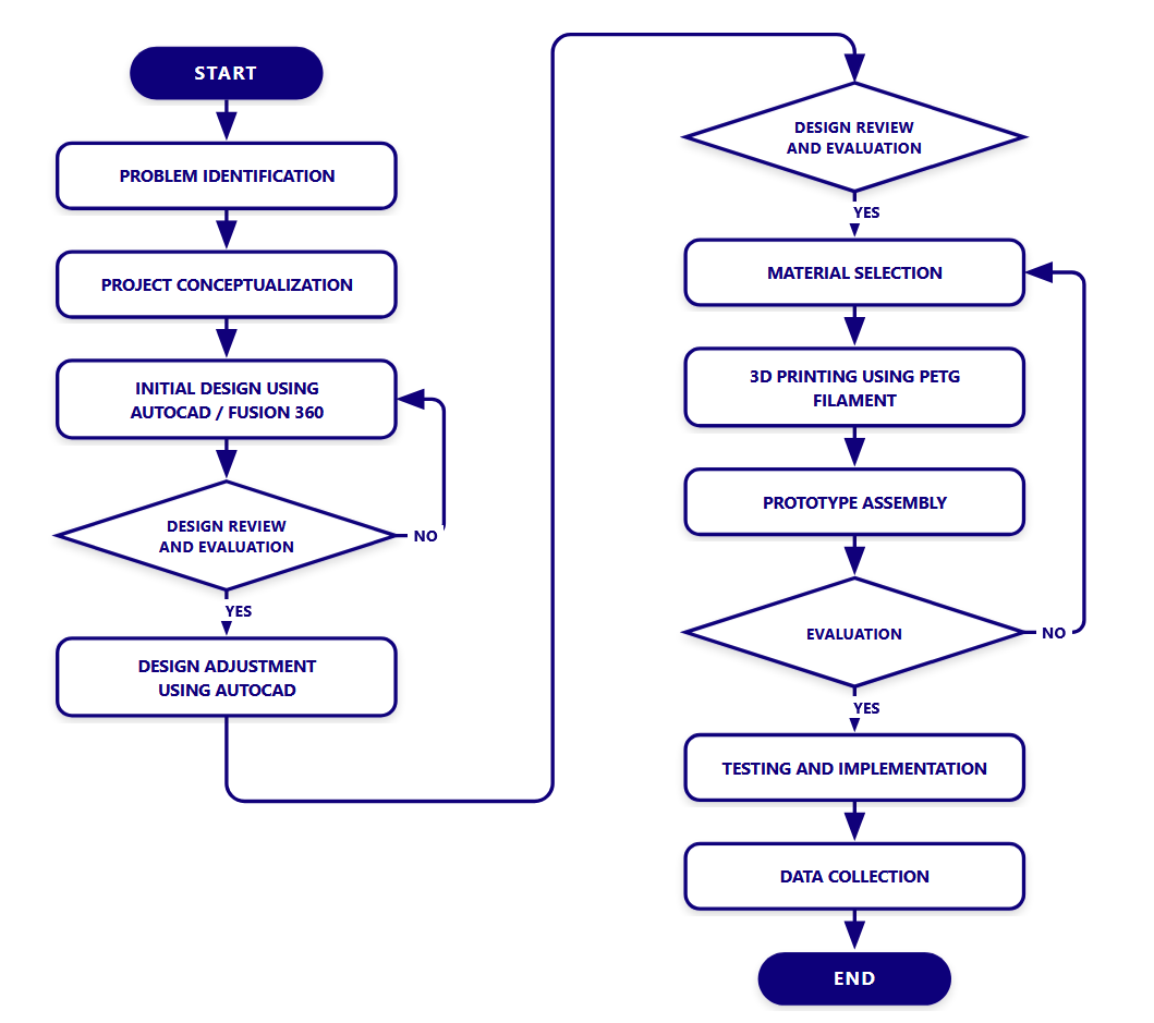
Process diagram: From problem identification to data collection
Development Process
Problem Identification
Identified the limitations of existing contour gauge designs — excessive bulk, lack of ergonomics, and impracticality for fieldwork.
Project Conceptualization
Brainstormed solutions focusing on reduced dimensions, modular features, and optimized geometry for portability.
Initial Design (TinkerCAD / Fusion 360)
Created digital models using CAD software. Evaluated design concepts for manufacturability and functionality.
Design Review & Evaluation
Iterative evaluation of prototypes. Adjustments made using AutoCAD based on feedback and testing results.
Material Selection
Selected PETG for structural components and TPU 90A for the centering mechanism based on strength, flexibility, and printability.
3D Printing
Components printed using PETG filament. Prototypes assembled and tested for fit and function.
Prototype Assembly
Assembled printed parts including iris mechanism, tube sliders, centering ring, and ohm-shaped stand.
Testing & Data Collection
Tested the gauge on different bamboo sizes (∅7, ∅8, ∅9, ∅10 cm). Collected data on accuracy, usability, and portability.
Materials & Tools
Materials
-
3D Filament (PETG)
Structural components
-
TPU 90A
Centering mechanism
-
Bamboo Samples
∅7-9 cm diameter
-
Hex Bolts & Nuts
Assembly hardware
Tools & Technology
-
Fusion 360 / Bambu Studio
CAD & slicer software
-
3D Printer
FDM printing
-
Caliper
Precision measurement
-
Saw
Bamboo cutting